





PCS, or Power Conversion System, is a bridge between the energy storage battery and the power grid, which not only realizes the conversion between DC and AC power but also provides precise power control and energy management according to the demand of the power grid and the state of the battery. In the context of the current energy transition, the development of energy storage technology is of great significance, and PCS, as the core component of the energy storage system, plays a key role in realizing the efficient storage and regulation of electric energy.
How The Power Conversion System PCS Works?
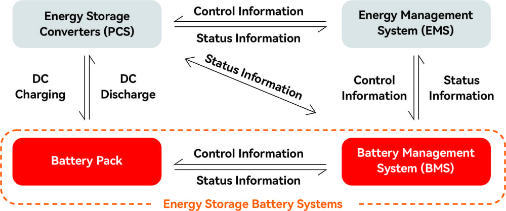
Power Conversion System PCS is mainly composed of power electronics, control and monitoring systems and batteries. Its principle is to realize efficient conversion and two-way flow of energy through power electronics to ensure stable operation and efficient utilization of the energy storage system. When the grid needs the energy storage system to discharge, PCS converts the DC power in the storage battery to AC power and outputs it to the grid; when the grid needs the energy storage system to charge, PCS converts the AC power in the grid to DC power and stores it in the storage battery.
Components and Structure of the Power Conversion System PCS
Components
It mainly includes power module, control module, filter circuit and protection circuit.
The power module is responsible for power conversion, the control module realizes operation monitoring and control, the filter circuit improves power quality, and the protection circuit ensures equipment safety.
Structure
Wall-mounted: Suitable for small-sized energy storage systems, easy to install and occupies little space.
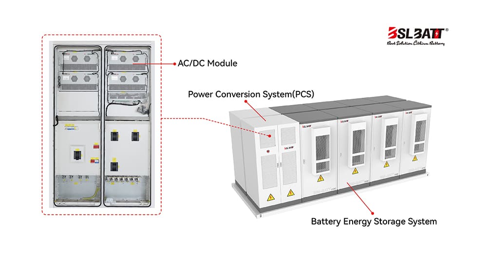
Cabinet type: suitable for medium and large energy storage systems, with high power level and reliability. Cabinet-type energy storage PCS usually consists of multiple power modules, which can be expanded and upgraded as needed.
Functions and Features of the Power Conversion System PCS
Function:
Two-way energy conversion, power control, power quality regulation. Charging and discharging power can be adjusted according to demand, reducing harmonics and electromagnetic interference.
Features:
Energy efficient, high reliability, intelligent control. High conversion efficiency reduces energy loss, modularized design is easy to maintain, and can be remotely monitored and managed.
Application Scenarios for Power Conversion System PCS
The classification of PCS application scenarios can be found in: What is the difference between PCS for large storage, commercial and industrial storage, and household storage?
The 3 Modes of Operation of the Power Conversion System PCS
The Power Conversion System (PCS) operates in the following three main modes: grid-connected mode, off-grid or isolated mode, and hybrid mode.
Grid-connected Mode / Realize two-way energy conversion between battery bank and power grid
In the grid-connected mode, the Energy storage system PCS realizes bi-directional energy conversion between the storage device and the grid according to the instructions of the host computer, and has the characteristics of an inverter.
Main role:
Prevention of islanding effect: automatically stops delivery in case of grid power failure. Synchronize grid operation: automatically track and synchronize grid voltage phase and frequency.
Through low voltage: maintain operation to cope with short-term reduction of the grid voltage source to guarantee the stability of the power system.
Off-grid or Island Mode / independent operation and power supply from the main grid
In off-grid or isolated mode, the storage PCS can operate independently from the main grid to provide local loads with AC power that meets the grid’s power quality requirements. For remote areas and emergency backup power systems, the off-grid or isolated mode is of irreplaceable significance to ensure power supply.
Main Role:
Autonomous power supply: independently provide AC power energy according to the set requirements.
Emergency power supply: Quickly switch to off-grid or lone-grid mode to cope with unexpected situations.
Hybrid Mode / Flexible switching between grid-connected and off-grid mode
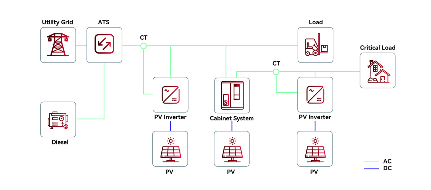
Hybrid mode allows the battery storage system to switch between grid-connected and off-grid modes, ensuring system reliability and flexibility to adapt to complex and changing grid environments.
Main Role:
Microgrid operation: When the microgrid is disconnected from the public grid, it can be flexibly switched to off-grid or isolated mode to secure power supply through the energy storage system in the microgrid.
Multi-functional application: it can realize filtering, stabilizing power grid and regulating power quality, self-healing faults, restoring and securing power supply.
Trends in Power Conversion System PCS
Higher performance, intelligent management and deep integration of multiple energy systems are the future trends of PCS.
High Power Density and High Efficiency Future PCS will adopt more advanced power semiconductor devices and heat dissipation technologies to improve power density and conversion efficiency, and reduce equipment cost and volume. At the same time, the application of 1500V system architecture will further enhance the energy density and system efficiency, and become the main technical solution to reduce costs and increase efficiency. Individual manufacturers proposed 2000V system program.
Intelligent and integrated PCS will tend to be intelligent, equipped with advanced control algorithms and sensors to achieve autonomous decision-making and optimized operation. In addition, PCS will be integrated with other key systems (such as energy storage battery, battery management system BMS, energy management system EMS, etc.) to improve system reliability and maintainability.
Multi-energy complementary and microgrid applications PCS will be applied with multiple forms of energy (solar, wind, hydro, etc.) in a complementary manner to realize diversified and sustainable development of energy. In microgrids, PCS will play an important role in ensuring stable operation and optimal control of microgrids to meet the specific needs of segmented scenarios.
Power Conversion System (PCS) vs. Energy Storage Inverter and Booster Inverter?
Power Conversion System (PCS):
PCS is the core equipment in the energy storage system, which is used to realize the energy conversion and bidirectional flow between the storage battery and the power grid. It can either be DC/AC converter (inverter function) or AC/DC converter (rectifier function).
It consists of DC/AC bi-directional converter, control unit, etc. The controller receives the background control instruction through communication, and controls the converter to charge or discharge the battery according to the symbol and size of the power instruction, realizing the regulation of active and reactive power of the power grid.
It converts the alternating current (AC) of the power grid into the DC power required by the battery, and converts the DC power stored in the battery into AC power to be supplied to the power grid.
Energy Storage Inverter:
An energy storage inverter focuses mainly on the inverter function, i.e. converting DC power to AC power. It is mainly used to convert the DC power in the storage battery into AC power to supply AC loads or to connect it to the AC power grid.
Booster Inverter:
The Booster Inverter is a highly integrated device that combines an energy storage converter (PCS) and a step-up transformer. The boost function is added on the basis of the two-way conversion of power in PCS, so that the stored power can be efficiently converted and boosted to meet the requirements of grid access.
Conclusion
Power Conversion System (PCS) is an important bridge in the battery energy storage system and an indispensable and vital part of the energy transition. Understanding what a Power Conversion System (PCS) does and how it works will help in the selection of a product.
If you have further questions, please consult with the professionals at BSLBATT, a manufacturer and supplier of commercial and industrial energy storage systems. Our turnkey commercial and industrial energy storage solutions include LiFePO4 battery packs, storage PCS, DC/DC, monitoring systems, fire protection systems, cooling systems and other important components that can be directly applied to a wide range of hybrid energy sources such as photovoltaic, utility and diesel. It can be directly applied to a variety of hybrid energy sources such as photovoltaic, utility and diesel.
Post time: Jan-08-2025