Views: 447 Author: Site Editor Publish Time: 2023-04-20 Origin: Site


Micro-grid (Micro-Grid), also known as micro-grid, refers to a small power generation and distribution system composed of distributed power sources, energy storage devices (100kWh - 2MWh energy storage systems), energy conversion devices, loads, monitoring and protection devices, etc., to supply power to the load, mainly to solve the problem of power supply reliability.

Microgrid is an autonomous system that can realize self-control, protection and management. As a complete power system, it relies on its own control and management for energy supply to achieve power balance control, system operation optimization, fault detection and protection, power quality management, etc. function.
The proposal of microgrid aims to realize the flexible and efficient application of distributed power, and solve the problem of grid connection of distributed power with a large number and various forms. The development and extension of microgrids can fully promote the large-scale access of distributed power sources and renewable energy, and realize the highly reliable supply of various energy forms for loads. Smart grid transition.
The energy storage systems in the microgrid are mostly distributed power sources with small capacity, that is, small units with power electronic interfaces, including micro gas turbines, fuel cells, photovoltaic cells, small wind turbines, supercapacitors, flywheels and batteries, etc. device. They are connected to the user side and have the characteristics of low cost, low voltage and little pollution. The following introduces BSLBATT's 100kWh energy storage system solution for microgrid power generation.

Energy Storage Converter PCS: 1 set of 50kW off-grid bidirectional energy storage converter PCS, connected to the grid at 0.4KV AC bus to realize bidirectional flow of energy.
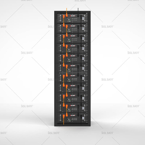
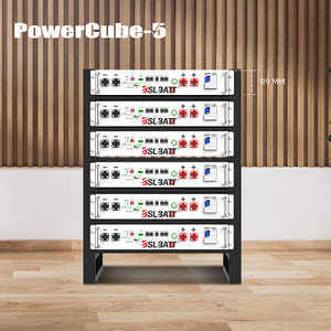
Energy Storage Battery: 100kWh Lithium iron phosphate battery pack, Ten 51.2V 205Ah Battery Packs are connected in series, with a total voltage of 512V and a capacity of 205Ah.
EMS & BMS: Complete the functions of charging and discharging control of the energy storage system, battery SOC information monitoring and other functions according to the dispatching instructions of the superior.
| Serial Number | Name | Specification | Quantity |
| 1 | Energy storage converter | PCS-50KW | 1 |
| 2 | 100KWh Energy storage battery system | 51.2V 205Ah LiFePO4 Battery Pack | 10 |
| BMS control box, battery management system BMS, energy management system EMS | |||
| 3 | AC distribution cabinet | 1 | |
| 4 | DC combiner box | 1 | |
● This system is mainly used for peak and valley arbitrage, and can also be used as a backup power source to avoid power increase and improve power quality.
● The energy storage system has complete functions of communication, monitoring, management, control, early warning and protection, and can continue to operate safely for a long time. The operating status of the system can be detected through the host computer, and it has rich data analysis functions.
● The BMS system not only communicates with the EMS system to report the battery pack information, but also directly communicates with the PCS using the RS485 bus, and completes various monitoring and protection functions for the battery pack with the cooperation of the PCS.
● Conventional 0.2C charge and discharge, can work off-grid or grid-connected.
● The energy storage system is connected to the grid for operation, and the active and reactive power can be dispatched through the PQ mode or droop mode of the energy storage converter to meet the grid-connected charging and discharging requirements.
● The energy storage system discharges the load during the peak electricity price period or the peak period of load consumption, which not only realizes the peak-shaving and valley-filling effect on the power grid, but also completes the energy supplement during the peak period of electricity consumption.
● The energy storage converter accepts the superior power dispatching, and realizes the charging and discharging management of the entire energy storage system according to the intelligent control of the peak, valley and normal periods.
● When the energy storage system detects that the mains is abnormal, the energy storage converter is controlled to switch from the grid-connected operation mode to the island (off-grid) operation mode.
● When the energy storage converter operates independently off-grid, it serves as the main voltage source to provide stable voltage and frequency for local loads to ensure uninterrupted power supply.
Advanced non-communication line voltage source parallel technology, supporting unlimited parallel connection of multiple machines (quantity, model):
● Support multi-source parallel operation, and can be directly networked with diesel generators.
● Advanced droop control method, voltage source parallel connection power equalization can reach 99%.
● Support three-phase 100% unbalanced load operation.
● Support online seamless switching between on-grid and off-grid operation modes.
● With short-circuit support and self-recovery function (when running off-grid).
● With real-time dispatchable active and reactive power and low-voltage ride-through function (during grid-connected operation).
● Dual power supply redundant power supply mode is adopted to improve system reliability.
● Support multiple types of loads connected individually or mixed (resistive load, inductive load, capacitive load).
● With complete fault and operation log recording function, it can record high-resolution voltage and current waveforms when fault occurs.
● Optimized hardware and software design, the conversion efficiency can be as high as 98.7%.
● The DC side can be connected to photovoltaic modules, and also supports parallel connection of multi-machine voltage sources, which can be used as a black start power supply for off-grid photovoltaic power stations at low temperatures and without power storage.
● L series converters support 0V startup, suitable for lithium batteries
● 20 years long life design.

If a single energy storage converter communicates, the RJ45 port of the energy storage converter can be directly connected to the RJ45 port of the host computer with a network cable, and the energy storage converter can be monitored through the host computer monitoring system.
On the basis of the standard Ethernet MODBUS TCP communication, the energy storage converter also provides an optional RS485 communication solution, which uses the MODBUS RTU protocol, uses the RS485/RS232 converter to communicate with the host computer, and monitors the energy through energy management. The system monitors the energy storage converter.
The energy storage converter can communicate with the battery management unit BMS through the host computer monitoring software, and can monitor the status information of the battery. At the same time, it can also alarm and fault protect the battery according to the status of the battery, improving the safety of the battery pack.
The BMS system monitors the temperature, voltage, and current information of the battery at all times. The BMS system communicates with the EMS system, and also directly communicates with the PCS through the RS485 bus to realize real-time battery pack protection actions. The temperature alarm measures of the BMS system are divided into three levels. The primary thermal management is realized through temperature sampling and relay-controlled DC fans. When the temperature in the battery module is detected to exceed the limit, the BMS slave control module integrated in the battery pack will start the fan to dissipate heat. After the second-level thermal management signal warning, the BMS system will link with the PCS equipment to limit the charge and discharge current of the PCS (the specific protection protocol is open, and customers can request updates) or stop the charge and discharge behavior of the PCS. After the third-level thermal management signal warning, the BMS system will cut off the DC contactor of the battery group to protect the battery, and the corresponding PCS converter of the battery group will stop working.
The battery management system is a real-time monitoring system composed of electronic circuit equipment, which can effectively monitor battery voltage, battery current, battery cluster insulation status, electrical SOC, battery module and monomer status (voltage, current, temperature, SOC, etc.), Safety management of the battery cluster charging and discharging process, alarm and emergency protection for possible faults, safety and optimal control of the operation of battery modules and battery clusters, to ensure safe, reliable and stable operation of batteries.
The battery management system consists of battery management unit ESBMM, battery cluster management unit ESBCM, battery stack management unit ESMU and its current and leakage current detection unit. The BMS system has the functions of high-precision detection and reporting of analog signals, fault alarm, upload and storage, battery protection, parameter setting, active equalization, battery pack SOC calibration, and information interaction with other devices.
The energy management system is the top management system of the energy storage system, which mainly monitors the energy storage system and load, and analyzes data. Generate real-time scheduling operation curves based on data analysis results. According to the forecast dispatch curve, formulate reasonable power allocation.
Device monitoring is a module for viewing real-time data of devices in the system. It can view real-time data of devices in the form of configuration or list, and control and dynamically configure devices through this interface.
The energy management module determines the energy storage/load coordinated optimization control strategy based on the load forecast results, combined with the measured data of the operation control module and the analysis results of the system analysis module. It mainly includes energy management, energy storage scheduling, load forecasting,
The energy management system can operate in grid-connected and off-grid modes, and can implement 24-hour long-term forecast dispatch, short-term forecast dispatch and real-time economic dispatch, which not only ensures the reliability of power supply for users, but also improves the economy of the system.
The system should support multi-level alarms (general alarms, important alarms, emergency alarms), various alarm threshold parameters and thresholds can be set, and the colors of alarm indicators at all levels and the frequency and volume of sound alarms should be automatically adjusted according to the alarm level. When an alarm occurs, the alarm shall be automatically prompted in time, the alarm information shall be displayed, and the printing function of the alarm information shall be provided. Alarm delay processing, the system should have alarm delay and alarm recovery delay setting functions, the alarm delay time can be set by the user set up. When the alarm is eliminated within the alarm delay range, the alarm will not be sent; when the alarm is generated again within the alarm recovery delay range, the alarm recovery information will not be generated.
Provide query, statistics, sorting and printing statistics of related equipment data, and realize the management of basic report software. The monitoring and management system has the function of saving various historical monitoring data, alarm data and operation records (hereinafter referred to as performance data) in the system database or external memory.
The monitoring and management system should be able to display performance data in an intuitive form, analyze the collected performance data, and detect abnormal conditions. Statistics and analysis results should be displayed in forms such as reports, graphs, histograms and pie charts.
The monitoring and management system shall be able to provide performance data reports of the monitored objects on a regular basis, and shall be able to generate various statistical data, charts, logs, etc., and be able to print them.
The monitoring and management system should have the division and configuration functions of system operation authority. The system administrator can add and delete lower-level operators and assign appropriate authority according to requirements. Only when the operator obtains the corresponding authority can the corresponding operation be performed.
The monitoring system adopts the mature multi-channel video security monitoring in the market to completely cover the operating space in the container and the observation room of key equipment, and supports no less than 15 days of video data. The monitoring system should monitor the battery system in the container for fire protection, temperature and humidity, smoke, etc., and perform corresponding sound and light alarms according to the situation.
The container cabinet is divided into two parts: the equipment compartment and the battery compartment. The battery compartment is cooled by air conditioning, and the corresponding fire-fighting measures are heptafluoropropane automatic fire-extinguishing system without pipe network; the equipment compartment is forced air-cooled and equipped with conventional dry powder fire extinguishers. Heptafluoropropane is a colorless, odorless, non-polluting gas, non-conductive, water-free, will not cause damage to electrical equipment, and has high fire extinguishing efficiency and speed.